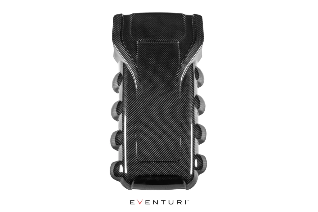
Audi B8 RS5 / RS4

Performance Gain: 15-20hp, 12-18ft-lb (At The Wheels)

Some of the photos above show our optional carbon engine and slam panel covers found HERE

The Audi RS5/RS4 Eventuri intake was developed after consultation and support from RS5 enthusiasts. We have completely re-engineered the inlet track from the ducts to the filters and the inlet tubes. The restrictive stock airboxes and duct feeds have been replaced with a highly efficient – fully sealed system with smooth transitions to allow the airflow to remain full and laminar. The resulting performance gains, sound and aesthetics are industry leading for this platform.

The Eventuri Difference

The RS5/RS4 Eventuri system uses our Patent Pending Carbon fibre Housings which provide an aerodynamically efficient airflow path from the filters to the throttle bodies. Not just another cone filter with a heat shield but a unique design which invokes the Venturi affect. You can read more about the housing design and how it works HERE

Categories:
Audi, Intake Systems, RS5
Below is an independent dyno graph showing the comparison between the Eventuri and the stock airboxes on a standard RS5. As you can see, power is increased through a large portion of the rpm range not just at the peak. This translates on the road to increased part throttle and full throttle response with the car pulling much more eagerly to the redline. The testing was done on the same day back-to-back and temperatures were monitored to ensure consistency. The car was tested firstly with the stock intake - hood closed. We then left the car on the dyno and installed the Eventuri. The car was then run again - hood closed. Several runs were carried out with both configurations to get a consistent result. Since dyno figures vary between runs - for fairness we chose to publish figures using the highest stock run VS highest Eventuri run. Here you can see the 2 best runs with both configurations.


We could have shown the highest figure achieved with the Eventuri VS the lowest achieved with the stock setup, however this would not be a fair comparison. Just to illustrate the variation, here is the graph showing highest Eventuri VS lowest stock which was recorded on the day showing a gain of over 32hp at the wheels.


Here is another graph showing the difference between the stock airboxes and the Eventuri intake system - this time on a B8 RS4. Dyno runs were done on the same day and the car remained strapped to the dyno during installation to ensure strap tensions were the same for both tests. Here we can see a considerable gain in both torque and power - with 25ft-lb toque gained in the midrange and 25hp gained before peak rpm.

Part Numbers:
  • EVE-RS5-INT : Audi B8 RS5/RS4 Black Carbon intake


  • The Eventuri B8 RS5/RS4 intake system consists of a number of components engineered to perform a specific purpose and fabricated to the highest of standards. Here are the details for each component and the design ethos behind them:

    Each intake system consists of:

    • 2 Carbon Fibre Venturi housings
    • 2 High Flow Double Cone Air Filters
    • 2 Aluminium Cowls for smooth airflow entry
    • 2 Carbon Fibre Inlet Tubes with integrated breather attachments
    • 2 Carbon Fibre Intake Ducts
    • 2 Carbon Fibre Front Scoops
    • 2 Laser Cut Stainless Steel Scoop Extension Plates
    • Laser Cut Heat Shields with Heat Reflective Lining
    • High Quality Silicon Couplers and OEM Spec Hose Clamps
    • Breather Hose Removal Tool


    Carbon Intake Housing Assemblies


    The filter housings comprise of the high flow filters, aluminium cowls, V-Band clamp, laser cut brackets and the carbon pods themselves. The carbon pods shroud the reverse mounted filter and smoothly shape the airflow down to the intake tubes. This smooth reduction in cross sectional area invokes the Venturi effect where the airflow accelerates whilst maintaining laminar conditions. It can be thought of as a large velocity stack - below is a diagram to show the comparison between our patent pending design and a regular intake system. Further details can be read in the Technology page.


    Carbon Fibre Intake Ducts


    The ducts channel ambient air from the scoops to the filter housings. They fit inside the OEM ducting system and smoothly transition to the circular filter housing shape. In order to ensure a good seal against engine bay heat - the ducts also have a flexible rubber edging around the openings which press against the filter housings creating the desired seal yet allowing the housings to move with the engine. These geometrically complex pieces are a key part of our B8 design.

    To illustrate - here is the left hand side intake assembled as it would be in the engine bay with the tube and duct:


    Carbon Fibre Intake Tubes


    Our intake tubes are again crafted from 100% prepreg carbon fibre. Each tube has an integrated breather tube insert which is CNC machined from aluminium. The tubes smoothly carry the airflow to the throttle bodies by ensuring there are no sharp or sudden bends. The smooth bend geometry ensure laminar flow is maintained from the filters to the exits.


    Carbon Fibre Air Scoops


    The final carbon components in this system are the front scoops - essential to direct ambient air to the ducts and then to the filters.

    The scoops were designed with a constant bend radius for maximum efficiency in directing the incoming air to the duct openings. They allow the inlet air temperatures to be as low as possible and increase the rate of drop in IATs after the system is heat soaked during a standstill.

    Heat Shields


    The heat shields serve two purposes - to deflect heat from the exhaust manifolds and to provide a mounting surface for the housings. Laser cut from stainless steel, the shields provide a strong mounting point to secure the housings to. Furthermore, by using a class leading reflective material on the reverse face, the shields effectively block radiant heat generated by the exhaust manifolds thus reducing the heat soak onto the carbon components.

    All the components come together in the engine bay to produce a genuine improvement in the driving experience as well as providing an incredible visual display of form and function in complete harmony. To add the finishing touches to the engine bay we have also produced matching carbon engine covers and slam panel covers. These items can be found HERE

    Optional Engine and Slam Panel Covers:

The RS5 Eventuri intake was developed over a number of months with every detail considered. Here you can read about our development process as it happened and the reasoning behind the design decisions we took.


We are redesigning the inlet track to be as aerodynamically efficient as possible in the given space. The standard airboxes are restrictive as they have a small rectangular filter which then has to transition very quickly to a circular tube. It is this transition which causes turbulence and hence increases the drag of the inlet track. Furthermore the ducts feeding the airboxes have deep pleats which again is not good for smooth flow. We will be implementing our Patent Pending Eventuri filter housings to provide a smooth transition from filter to inlet tube.

All carbon components will be made from prepreg carbon fibre for strength and for minimising heat transfer to the airflow.

Mated to the Eventuri housing will be a carbon fibre tube which will smoothly run to and match the diameter of the throttle body. We use CF because it is a great insulator across its thickness. Aluminum tubes could be used however this is more than 400 times worse than CF at insulating the intake air from engine bay heat!

Finally in order to feed the filter housing with cold air - we are designing ducts which connect to the OEM front ducts and then smoothly transitions to the mouth of the housing. To further improve the cold air feed we are designing extensions for the stock intake ducting behind the grill to act like scoops. Since the filter housing will be rigidly mounted to the engine via the carbon tube, we won't be attaching the housing to this duct - there needs to be some flexibility in the system so we are working on a floating type mount where the duct will simply nest the housing allowing some movement.

Here are some CAD images of the system currently in development (scoop extensions not shown yet):


Here are the first 3D printed parts in place - clearly the space is very restricted so we are optimising the filter housing for maximum volume in the given envelope.


Update:

After a number of iterations we have finalised the filter housing shape and size. It fits neatly in the engine bay yet has sufficient volume and length to allow the airflow to transition smoothly to the intake tubes for the throttle bodies. Here are the prepreg carbon housings:


Update:

We finished the left hand side (as you look at the engine) and finalised the way in which the intake housing mates to the duct to allow engine movement. Basically the carbon tube and housing will be mounted to the engine and so will move with the engine - the duct which is attached to the stock ducting will not be attached to the housing but rather will have a rubber extrusion sealing against the filter housing. This allows movement and also ensures no hot air is drawn in by the filters.

The right hand side is almost finalised now - there is less space here due to the aircon pipes and so we had to spend some time getting the angles right. Here are some photos with the carbon housings and 3D printed tubes and ducts in place:


The final pieces are the scoops which will protrude from the stock ducting into the front grill. We have seen other attempts at making scoops and they are simply too flat for effective channeling of air into the ducts. Our scoops have been designed with a continuous curve so that the oncoming air meets a curve and is forced into the duct rather than meeting a flat surface and causing turbulence.

The scoops will protrude right up to the grill and so will be visible from outside - as these will be carbon, they will provide a nice visual touch - hinting at what is under the hood.

Here are the CAD images of the scoops under development:


CFD and CAD

The CFD simulations show the airflow characteristics through one side. You can see that the flow is smooth with minimal turbulence - importantly through the tubes, the flow is full and steady. The velocity of the airflow is shown by colour - blue is slowest and red fastest. There is a steady increase in velocity through the system as the cross sectional area reduces smoothly which is as expected and it all bodes well so far for the real test!

CFD:


CAD:


Update

The carbon tubes and filter housings will be mounted to the engine by using the studs which currently hold the OEM bracket for the airbox.

There are 2 brackets - one mounted to the housing directly and then the other mounted to the engine. Since the exhaust manifolds are exposed in the airbox area - we designed the engine bracket to extend and cover the manifolds to minimise direct radiant heat transfer.

The carbon intake tube and housing will move with the engine - the carbon duct is mounted to the OEM front ducting and is connected to the housing by a rubber seal - so allows for movement as it isn't rigidly mounted to the housing.

All brackets will be laser cut from stainless steel and then powder coated to improve appearance and heat insulation properties.

Some CAD images:


With development completed, the carbon fabrication commenced and final component details can be seen with descriptions in the "Product Details" tab.
Intake sound recorded in the cabin with OEM sports exhaust.

STOCK INTAKE

EVENTURI INTAKE


Please download the RS5 installation manuals here. You can also view a short guide on the breather hose removal here too.


Download Installation Guide

audi intake B8 intake b8 rs4 intake B8 rs5 intake RS4 performance RS4 TUning RS5 CAI RS5 performance RS5 tuning